 Buying Guide
Compare 10 Canadian playground equipment manufacturers and suppliers by manufacturing evidence, product focus, regional support, CSA documentation and project fit.
Read insight


A narrow courtyard, an L-shaped boundary, a slope or a site interrupted by trees does not automatically rule out a commercial playground. It does, however, change the planning process. Instead of selecting equipment first, the project should begin with an accurate site record and a layout that coordinates play value, circulation, safety clearances, drainage, access and installation.
Published by ZZRS Amusement Equipment Co., Ltd. (ZZRS Playground).
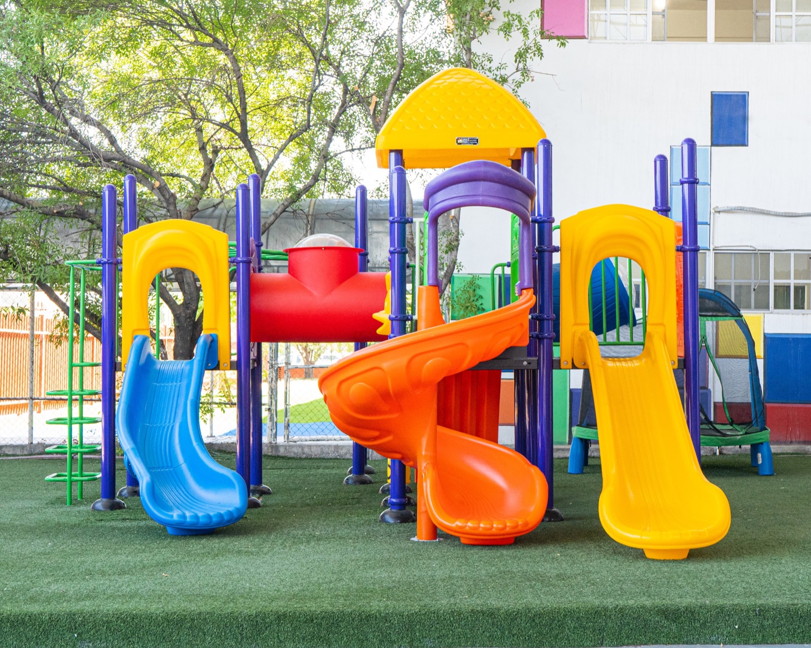
Compact playground configurations can use available space efficiently while preserving access, supervision and equipment clearances.
Quick Answer
Yes, playground equipment can be customized for irregular sites. The design should be based on accurate site dimensions, boundaries, entrances, existing buildings, trees, slopes, drainage, safety zones, target age group and installation conditions.
For buyers, developers, schools and landscape teams, the important question is not simply “Will a playground fit?” It is “What configuration will fit safely, install practically and deliver worthwhile play within the available site?” This guide explains the information and decisions needed before a custom layout is approved.
An irregular playground site is any space where a conventional rectangular equipment footprint cannot be placed without additional design review. The challenge may be the outline of the land, the usable area inside that outline or the conditions that affect delivery and installation.
Common examples include:
Narrow and long spaces between buildings, paths or boundary walls
L-shaped, curved, triangular or segmented plots
School, hotel or residential courtyards with limited access
Sloped sites or sites with more than one finished ground level
Areas that must retain mature trees, lighting, drainage points or other fixed facilities
Limited residential spaces where supervision and noise-sensitive boundaries matter
Sites with restricted gates, corridors, lifting positions or temporary storage
Two plots with the same total area may support very different playgrounds. A usable rectangle with clear delivery access is not equivalent to a courtyard of the same area divided by trees, columns and pedestrian routes. Planning must therefore be based on the usable envelope rather than the headline site area.
The quality of a custom layout depends on the quality of the site information. A rough length and width can support an early discussion, but it is usually not enough for production approval.
Prepare the following information where available:
Site dimensions: overall length and width, boundary segments, corners, level changes and clear heights
CAD, PDF or dimensioned sketch: show the scale and mark all fixed objects
Photos and video: capture every boundary, entrance, adjacent building and the route from unloading point to installation area
Entrances and exits: include gate, corridor and door widths and heights
Existing conditions: buildings, trees, columns, utilities, lighting, drains, retaining walls and underground restrictions
Ground information: finished surface, soil or slab condition, slope and drainage direction
Users: intended age group, expected operating pattern and any inclusive-play objectives
Project brief: preferred theme, priority play activities, budget range and target schedule
Installation plan: local contractor capability, lifting access, storage area and working-hour limits
The ZZRS site planning guide and quotation information checklist can help organize this material before the first layout review.
A useful layout starts by dividing the site into zones rather than filling every available square meter with equipment. The main structure is only one part of the plan. Circulation, supervision, slide exits, safety surfacing and maintenance access also require clear space.
A practical review normally considers the following sequence:
Define the usable envelope. Remove building offsets, retained trees, utilities, drainage channels and access routes from the nominal site area.
Position the primary play element. Orient entrances, stairs and climbing access toward the main circulation and supervision zones.
Protect movement paths. Keep slide exits and active play routes away from gates, walls, seating and crossing traffic.
Check sightlines. Avoid creating hidden pockets behind solid panels, landscaping or building corners.
Reserve maintenance access. Allow technicians to inspect fasteners, foundations, decks and moving parts after installation.
Coordinate surfacing and drainage. The impact-attenuating surface, edges, slopes and water flow should be planned as one system.
On a constrained site, a smaller well-organized configuration often performs better than a larger structure compressed into the boundary. The goal is not maximum equipment density; it is a coherent play route that remains understandable to children, supervisors and installers.
Not every irregular site needs a completely new structure. The right customization level depends on the boundary, required functions, budget and documentation scope.
| Approach | Best suited to | Planning note |
|---|---|---|
| Standard structure | Sites with a clear usable rectangle | Fastest starting point, but its complete footprint and clearances must fit |
| Modular configuration | Narrow, long or partly obstructed sites | Platforms, bridges, climbers and slides can be rearranged within approved technical limits |
| Freestanding mix | Separated pockets or sites with retained features | Individual components can distribute play value without forcing one large footprint |
| Fully custom structure | Complex boundaries, architectural themes or unusual level changes | Requires detailed layout, structural and production review before approval |
| Multi-level architectural play | Projects that can use height more effectively than ground area | Must coordinate clear height, access, supervision, evacuation and installation |
A custom playground design process should keep the visible concept, technical specification and approved quotation aligned. A 3D image is useful for communication, but it does not replace dimensioned layout and production documents.
Limited ground area does not necessarily mean limited play variety. The design can combine different movement and sensory experiences without adding a large number of separate structures.
Useful strategies include:
Use vertical space with connected platforms at carefully reviewed levels
Link activities with elevated bridges or compact transition panels
Select tube or turning slides where their complete exit area can be positioned safely
Combine climbing nets, steps and access challenges instead of repeating one route
Add interactive panels, role-play details or sensory activities to platform walls
Use suitable under-platform zones for low-level activities where visibility is maintained
Fill separate small pockets with compact freestanding play instead of oversizing the main unit
Every additional function should earn its place. A route that creates a bottleneck, blocks supervision or pushes an exit into a circulation path may reduce the value of the overall design even if it increases the equipment count.
Irregular boundaries do not reduce the need for equipment clearances. Required safety zones must be reviewed for the selected equipment, intended users, destination and applicable project requirements. They should be shown on the layout rather than estimated after the structure has been placed.
The review should cover:
Fall zones and impact-attenuating surfacing around elevated or active play elements
Clear slide run-out and exit areas
Movement clearance around swings, rotating or other moving equipment
Guardrails, barriers, openings and access appropriate to the selected configuration
Supervision visibility from entrances, seating and main pedestrian routes
Separation of activities intended for different age or ability groups where required
Transitions between impact surfacing, paths, curbs, drains and surrounding landscape
Planning note: Do not approve a layout from the visible equipment outline alone. Ask for the safety-zone drawing, final dimensions and the exact configuration covered by the project documents.
A structure can fit on the final drawing and still be difficult to install if the delivery route has not been checked. Courtyards and sites surrounded by completed buildings are particularly sensitive to component size, lifting access and installation sequence.
Confirm these items before production and shipment:
Whether the largest posts, slides, panels and platform assemblies can pass through every gate and corridor
Whether cranes, forklifts or manual handling are permitted and where lifting equipment can stand
Foundation type, finished levels, slope correction and underground services
The installation sequence when there is only one narrow access point
Temporary storage for classified components, hardware and packaging
Protection of completed paving, walls, planting and adjacent facilities
Coordination between the playground supplier, local contractor, surfacing team and site manager
For complex structures, the need for factory trial assembly should be agreed during technical review. Trial assembly can help verify interfaces and component identification, but the exact scope depends on the selected product and project requirements.
ZZRS reviews irregular-site projects as a coordinated design and delivery task. Support can be defined according to the project scope and may include:
Review of site dimensions, photos, CAD files and access conditions
Preliminary layout and circulation discussion
CAD drawings and 3D rendering for an approved design direction
Custom structure, theme, color and selected play-function development
Material and finish definition through the project specification
Production review and trial assembly when agreed and technically appropriate
Classified packing, component identification and shipping preparation
Installation drawings and online technical guidance according to the quotation
The final layout, materials, documentation, packing method and installation support should always be confirmed in the approved specification and quotation. This keeps assumptions from the early concept stage from being treated as final production commitments.
Yes. A standard model may be rearranged, modular components may be combined or a fully custom structure may be developed. The appropriate option depends on the usable boundary, safety zones, target users, access, budget and project requirements.
Provide all boundary lengths, corners, clear heights, entrances, level changes and the positions of buildings, trees, drains, utilities and other fixed objects. A dimensioned CAD, PDF or sketch plus photos and access video is preferable.
Linear modular structures, compact towers, connected platforms, selected climbers, wall panels and small freestanding elements can work well. The exact choice must be checked together with slide exits, circulation and safety clearances.
Yes, where the site, supervision plan, access and selected configuration allow it. Multi-level platforms and elevated connections can add play value, but height, guard protection, clearances and installation must be reviewed as part of the complete design.
They are drawn around each relevant activity according to the selected equipment and project requirements. If the available site cannot accommodate the required zones, the equipment selection or layout must change; the clearances should not simply be compressed.
Local installation may be possible when the team has suitable construction capability and receives the agreed drawings, component identification and technical guidance. The installation method, tools, foundations and support scope should be confirmed before ordering.
Start with the site
Send ZZRS your site dimensions, CAD or sketch, photos, access information, destination, target users and preferred play functions. The team can review a suitable standard, modular or custom direction for your project.
Request a Project ReviewPractical guidance from playground planning, manufacturing, delivery and completed project experience.
Buying Guide
 Buying Guide
 Factory & Production